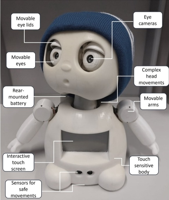
Interactive Robot
Pediatric vision therapy and educational programs often rely on static screens and brief clinician instructions, leaving many young patients bored, disengaged, and at risk of abandoning treatment . Research from the University of Waterloo’s Social and Intelligent Robotics Research Lab shows that humanoid platforms like MIRRLY can capture children’s attention with lifelike facial expressions and interactive games, yet most existing solutions remain too expensive or complex for routine clinical and home use. This project tackles these challenges by applying a human-centered, iterative design methodology to deliver an affordable, modular humanoid robot with intuitive controls and customizable behaviors, aiming to boost engagement and improve adherence in pediatric therapy.
Objective: Design and build a robot for graduate‑level studies on how children with disabilities interact socially with robots. The robot must have the following attributes.
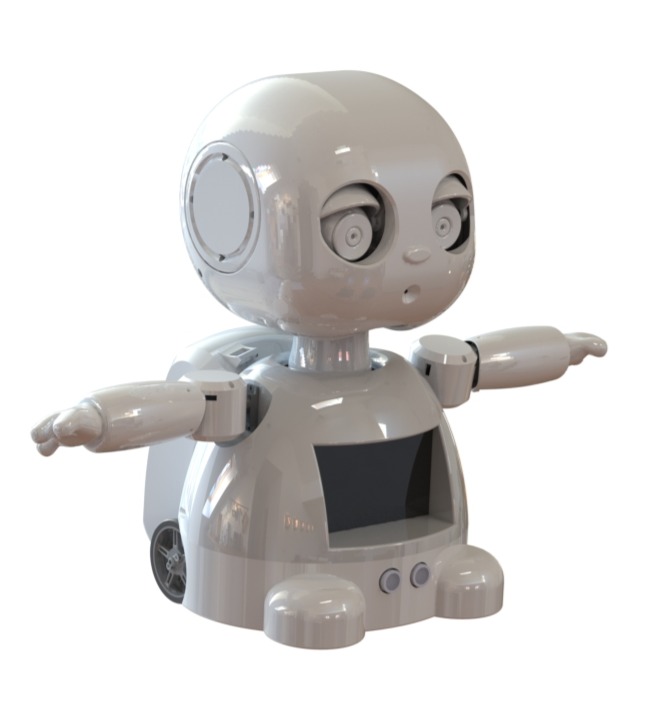
- Detects facial expressions
- An interactive touchscreen
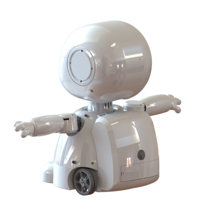
- Use edge detection to avoid falls
- Show friendly eye and neck motions
- Have speakers and a microphone for sound interaction
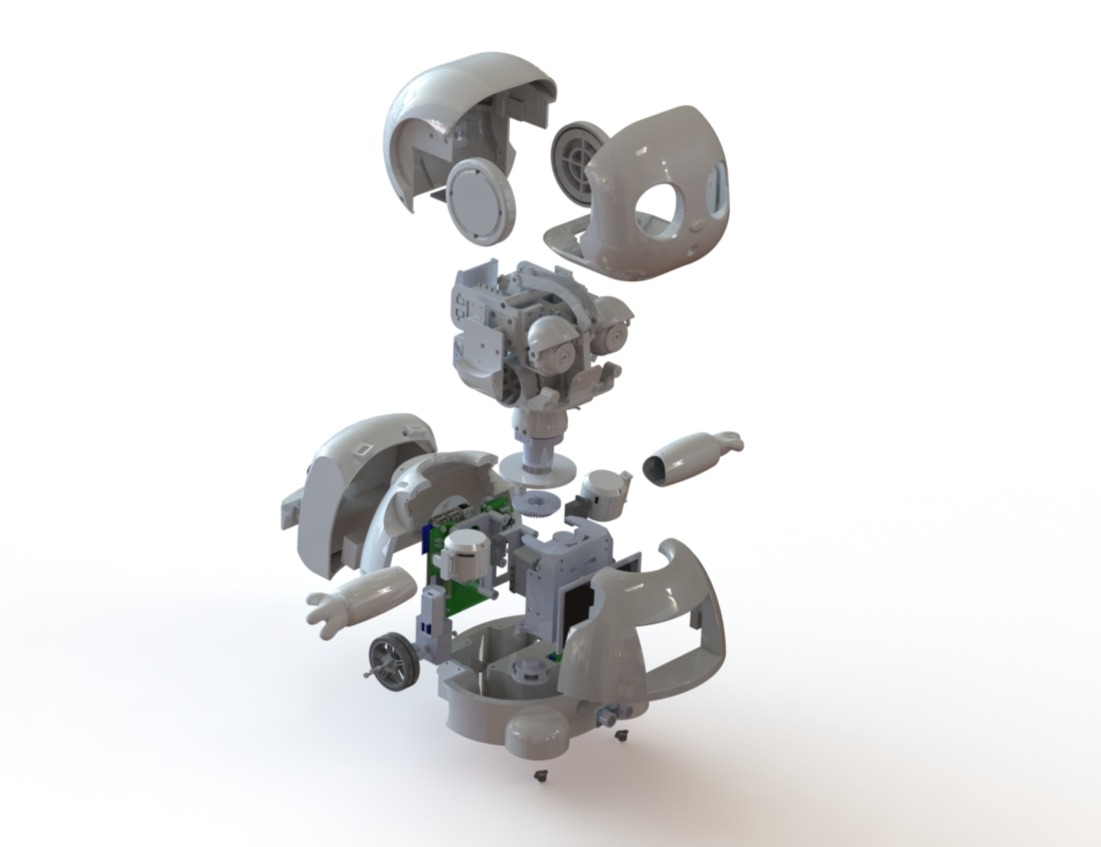
Mechanical Design
Process:
- Inspected and analyzed the first generation MIRRLY robot to catalog mechanical failures such as a misaligned neck, taped mounts, thin walled shells and suboptimal sensor placements forming the basis for targeted redesign.
- Defined design constraints for functionality and manufacturability, specifying motor torque requirements, sensor integration parameters, minimum wall-thickness standards, and a professional aesthetic.
- Engineered the shell and chassis in SolidWorks to ensure proper clearances, structural integrity, correct interference fits, and compliance with wall-thickness requirements, achieving a product-ready appearance.
- Integrated the stack-up of electrical components into the robot’s body.
- Ordered 3D-printed components at production-grade resolution and assembled them to complete the final robot.
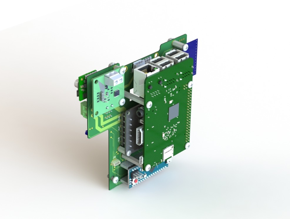
Electrical Design
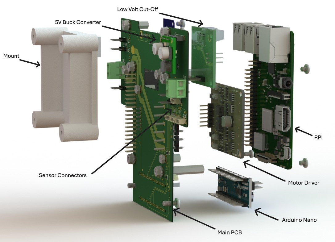
Process:
- Designed in Altium, with schematics and multilayer PCBs created to integrate DC motors, a motor driver, touch sensors, IMUs, time-of-flight and ultrasonic sensors, eye cameras, speakers, a touchscreen, a microphone, an Arduino, a Raspberry Pi, a buck converter, a 12 V LiPo battery, and a low-voltage cut-off switch.
Used SolidWorks to model the stack-up of electrical components to fit within the robot’s body.
- Implemented battery monitoring with a voltage divider and RGB LED on the Arduino ADC for real-time level indication.
- Hand-soldered the PCBs and wires.
- Developed initial controller firmware to test and validate all connections to peripheral devices.
Firmware Design
Process:
- Developed firmware for all sensors and actuators to confirm that the electrical system is functioning properly.
Finished Product

Results, Testing & Validation
- Full system pass‑off — all sensor nodes and 8 actuators passed bench tests for I²C/UART traffic, PWM response, and fault‑free operation over 24 h burn‑in.
- Battery monitor accuracy ±0.05 V — voltage‑divider readings matched a calibrated DMM across 0–11.1 V.
- Reliable edge avoidance — time‑of‑flight board stack detected 100 % of drop‑offs ≥30 mm in 50 tabletop trials.
- Peer‑review validation — hardware methods and data accepted at ACM HAI 2024 (36 % acceptance rate).
- Educational impact — the finished robot served as the core apparatus for a master’s thesis and helped the student successfully defend and earn their degree in 2025.